哈德沃角码
+86 13590665616
The solar panel quick fastening clip middle clamp is a key component in the installation of photovoltaic systems. It is mainly used to fix the middle position of two adjacent solar panels, ensuring a stable connection of the components on the track or bracket. Its working principle usually combines mechanical clamping, sliding positioning, and fastening locking. Different designs may vary slightly. The following is a detailed analysis of the core principles:
I. Basic Structure and Installation Scenarios
The solar panel quick fastening clip middle clamp is generally composed of the following components:
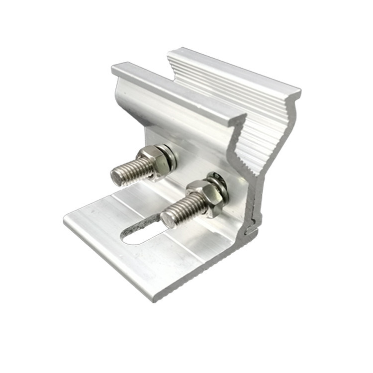
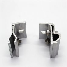
Main clamping block: It is used to directly clamp the frame of the solar panel (usually an aluminum alloy frame).
Sliding parts: Such as sliders and rail connectors, which are used for positioning and sliding on the bracket track.
Fastening device: Such as bolts, set screws, nuts, or spring structures, which are used to lock the position of the fixture.
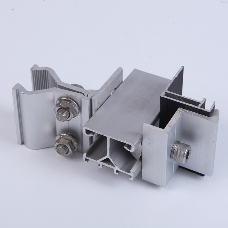
Application scenarios: Installed in the middle of the adjacent edges of two solar panels, the solar panel frame is fixed to the supporting rail below through the solar panel quick fastening clip middle clamp, forming an integral array.
II. Core Working Principles
1. Sliding Positioning: Quickly Adjusting the Position on the Track
The solar panel quick fastening clip middle clamp is usually connected to the track of the photovoltaic support (such as an aluminum alloy guide rail) through a slider or snap - fit structure. During installation, the fixture can slide transversely along the track, and its position can be adjusted flexibly to meet the requirements of different - sized panels or installation spacing.
2. Mechanical Clamping: Fixing the Frame of the Solar Panel
The design of the main clamping block needs to match the cross - sectional shape of the solar panel frame (usually rectangular or trapezoidal), and the clamping is achieved through the following methods:
Top clamping: The top of the clamping block extends horizontally on both sides to form "clamping parts", pressing the upper surface of the solar panel frame from above, and the bottom is supported by the track, forming an up - down clamping force.
Side clamping: Some fixtures clamp the frame from the side by the opposite extrusion of the left and right clamping blocks (similar to a tiger - mouth structure), which is suitable for solar panels with frameless or special frame designs.
Key principle: Utilize the friction between the clamping block and the frame to resist the horizontal displacement of the solar panel (such as wind force and vibration), and at the same time, lock the position in the vertical direction through the fastening device.
3. Fastening Locking: Fixing the Fixture by External Force
After the sliding positioning is completed, the fixture needs to be fixed to the track and the solar panel as a whole through the fastening device. Common methods include:
Bolt/Set - screw locking: By turning the set - screw (such as the "second set - screw" in the "Manufacturing Method of Solar Photovoltaic Panel Fixing Structure"), the slider or clamping block is pushed to closely adhere to the inner wall of the track, and the position is fixed by friction. Set - screws are usually equipped with spring washers to prevent loosening due to vibration.
Spring/Clip locking: Some quick - acting fixtures adopt an elastic structure (such as a spring plate). During installation, the fixture is directly pressed, and the spring deforms to generate a clamping force, which can be quickly fixed without tools (suitable for temporary installation or maintenance scenarios).
Nut and track groove cooperation: The nut at the bottom of the fixture is embedded in the T - shaped groove or C - shaped groove of the track. A bolt passes through the main body of the fixture from above and tightens the nut to lock the fixture on the track (such as the common "T - shaped middle fixture").
END
Tel.:+86 13590665616
E-mail: sunnyxiulan@gmail.com

Copyright© Foshan Xuanqing Hadewo Home Technology Co., Ltd. 粤ICP备2021103218号 Technical support:Yunlu Technology